
RW technical knowledge
Railway voltage limiting devices: principles, selection and monitoring
Understand how VLDs limit touch voltage, how class 2.1 differs from class 2.2, and what recoverable current ratings mean for railway applications.
A voltage limiting device connects the railway return circuit to a protected conductive structure when defined voltage conditions are reached. Its selection affects touch‑voltage protection, fault behaviour and the paths through which current can flow.
Protection and return‑current paths
Why railways use voltage limiting devices
Limit hazardous touch voltage
Return current can produce a voltage difference between the rails and nearby conductive structures. Depending on the traction system and installation, a VLD limits this difference by establishing a conductive connection when its triggering conditions are met.
Applications include passenger platforms, traction substations and trackside structures. The voltage thresholds, current paths and protection requirements must be evaluated for each installation.
Distinguish operation from fault behaviour
VLD‑O addresses operational touch‑voltage conditions; VLD‑F addresses fault conditions. A VLD‑O+F combines these functions within its specified limits.
A recoverable VLD can return to its non‑conductive state after the event under the required reset conditions. A non‑recoverable activation or overload can leave a device permanently conductive and require replacement. A conductive connection is therefore not always temporary.
Operating principles
VLD classes in the RW portfolio
Class identifies the operating principle, not just a current rating. In particular, a higher‑current class 2.1 model does not become a bipolar class 2.2 device.
Class 1 · VLD‑F
Fault protection using a spark‑gap principle. A destructive fault activation can create a permanent conductive connection; the affected device must then be identified and replaced.
Do not compare a non‑recoverable fault‑withstand value directly with a class 2 recoverable rating.
Explore RWVL1 →Class 2.1 · VLD‑O+F
RWVL2.1 and RWVL2.1HP use one primary thyristor switching polarity for DC traction. Integrated varistors provide surge protection.
Reverse‑polarity loads, regeneration and the fault envelope require application review; longer reverse‑polarity events can overload the varistors.
Explore RWVL2.1 and NEW HP →Class 2.2 · VLD‑O+F
RWVL2.2 and RWVL2.2HP use two anti‑parallel power thyristors for recoverable operation in both voltage polarities, within their rated limits.
These bipolar devices support DC and AC traction, including operational and defined fault conditions.
Explore RWVL2.2 and NEW HP →This is an overview of the RW portfolio, not a complete reproduction of the standard's classification. Product selection remains application‑specific.
Compare like with like
Current, duration and recoverability belong together
A current value without its duration and recovery condition is not a useful performance comparison. Keep recoverable short‑time current, non‑recoverable fault withstand and impulse ratings separate.
Scroll horizontally to compare all models →
| Model / class | 50 ms | 100 ms | 30 s |
|---|---|---|---|
| RWVL2.1 · class 2.1 | 25 kA | 18 kA | >3 kA |
| RWVL2.1HP · class 2.1 · NEW | 34 kA | 24 kA | >3 kA |
| RWVL2.2 · class 2.2 | 25 kA | 18 kA | >3 kA |
| RWVL2.2HP · class 2.2 · NEW | 34 kA | 24 kA | >3 kA |
The first two columns are short‑time ratings; the 30 s column is a long‑time recoverable rating. See the model‑specific datasheets for triggering variants, thermal conditions, rated current and other limits.
From a world‑leading 25 kA platform to 34 kA. RW class 2 models already held the market‑leading position at 25 kA at 50 ms. The HP versions raise this rating by 36% to 34 kA at 50 ms, the highest published recoverable short‑time current identified in VLD class 2.
This comparison concerns published recoverable ratings at the specified duration, not non‑recoverable class 1 fault values or impulse ratings.
Stray current, conductive states and corrosion
In DC traction, current leaving the intended return circuit can flow through surrounding conductive structures. Corrosion exposure depends on the current paths, magnitude, duration and local conditions.
A VLD must create a conductive path when required for protection. The maintenance concern is an unintended prolonged connection, including a failed device that remains conductive after the event.
Immediate fault identification allows the operator to target the affected VLD for replacement. Shortening this period can reduce the associated stray‑current corrosion risk. Monitoring provides the information; the maintenance action removes the failed device.
Measured operating behaviour
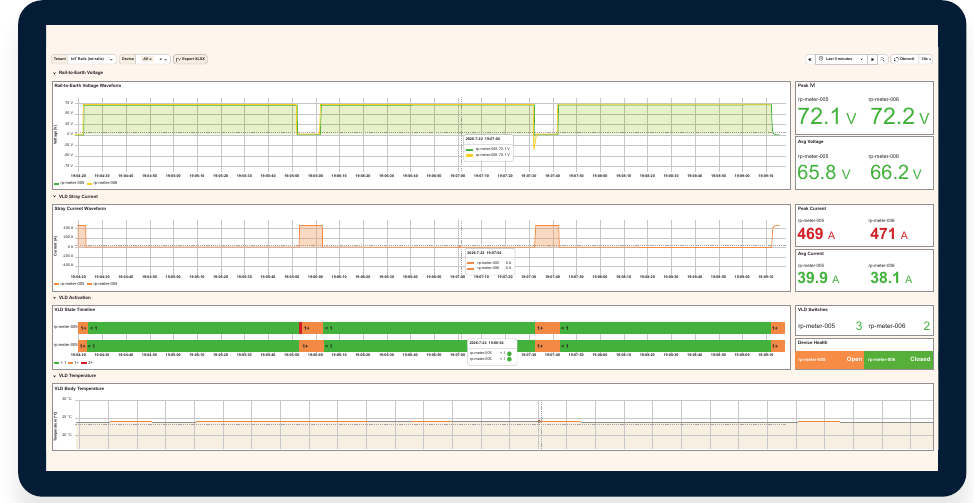
See voltage, current and activation together
RWVLM Online Measurement and Monitoring records rail‑to‑earth voltage and VLD current. Its specified DC measurement ranges are ±400 V and ±1000 A, with a 1‑second sampling interval and LTE‑M (NB‑IoT) communication.
Use events to guide maintenance
Voltage and current trends show when the VLD conducts, how long an event lasts and whether patterns repeat. Email, SMS and system alerts notify the operator of detected faults and support targeted maintenance.
The monitoring configuration and installation must be compatible with the connected VLD. RWVLM can be used with RW or compatible third‑party devices after integration review.
RWVLM FT: monitoring and forced VLD switch‑off
RWVLM FT combines measurement and monitoring with its own integrated switch‑off mechanism. It can force the connected VLD to switch off, including VLDs from other manufacturers, without relying on a dedicated control function in the VLD itself.
The specified switch‑off current range is 20–80 A, with a lifetime above 100,000 cycles. The switch‑off mechanism is part of the FT monitoring hardware.
What to check before selecting a VLD
- Traction system and polarity. DC or AC, normal and fault polarities, regeneration and return‑circuit arrangement.
- Triggering conditions. Nominal and instantaneous triggering voltage, non‑triggering voltage and applicable installation requirements.
- Current envelope. Current amplitude, duration, repetition, recovery conditions and coordination with traction protection.
- Installation and maintenance. Ambient temperature, heatsinks, enclosure, access, monitoring and response to a failed device.
For suitable applications, an RW class 2 VLD can be a technically appropriate and cost‑effective alternative to class 4. This requires application‑specific engineering review; current rating alone is not a substitution rule.
Frequently asked technical questions
What is the difference between VLD‑O and VLD‑F?
VLD‑O addresses excessive touch voltage arising during operation. VLD‑F addresses fault conditions. A VLD‑O+F device combines these functions within its specified application and current limits.
How do class 2.1 and class 2.2 differ?
RW class 2.1 devices use one primary thyristor switching polarity for DC traction. RW class 2.2 devices use two anti‑parallel thyristors for bipolar operation in DC and AC traction. Class selection must account for polarity, regeneration and the expected fault envelope.
What does recoverable current mean?
A recoverable rating specifies the current and duration the VLD can withstand while retaining its intended recoverable function under the specified conditions. It is not interchangeable with a non‑recoverable fault rating or a lightning impulse rating.
What do the new HP models add?
RWVL2.1HP and RWVL2.2HP provide 34 kA at 50 ms and 24 kA at 100 ms recoverable short‑time current, compared with 25 kA and 18 kA for the respective standard models. Both HP models provide more than 3 kA for 30 seconds. Their class 2.1 and class 2.2 operating principles remain distinct.
Can monitoring help reduce stray‑current corrosion risk?
Monitoring can identify a failed, continuously conducting VLD so that the affected device can be replaced promptly. This can shorten the period of unintended stray‑current flow. Monitoring supports the maintenance response; measurement alone does not eliminate corrosion.
What does the RWVLM FT hardware version add?
RWVLM FT adds an integrated forced switch‑off mechanism to measurement and monitoring. The mechanism is built into the FT hardware and can force the connected VLD to switch off, including VLDs from other manufacturers. The VLD itself does not need a dedicated switch‑off control function. The specified switch‑off current range is 20–80 A.
Technical sources and further reading
Product values on this page refer to the following English RW datasheets. The VLD product standard referenced by these datasheets is EN 50526‑2; touch‑voltage and installation requirements must be assessed against the applicable railway standards and national rules.
- RWVL2.1 datasheet — PDF
- RWVL2.1HP datasheet — PDF
- RWVL2.2 datasheet — PDF
- RWVL2.2HP datasheet — PDF
- RWVLM Online Measurement and Monitoring datasheet — PDF
Discuss the application with RW
For product selection, share the traction‑system details, required triggering voltage, expected current profile and monitoring requirements.
Contact technical sales