
RW class 2.1 · DC traction
Two models. Recoverable performance up to 34 kA.
RWVL2.1 and the new RWVL2.1HP limit excessive touch voltage in DC railway traction systems. Both are VLD‑O+F class 2.1 devices with one primary switching polarity and integrated A2 surge protection.
Choose RWVL2.1 for a recoverable short‑time current of 25 kA at 50 ms, or RWVL2.1HP for 34 kA at 50 ms. Both meet EN 50526‑2 requirements.
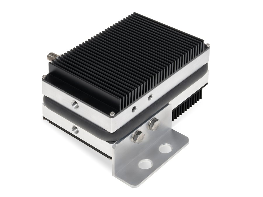
RWVL2.1
Recoverable short‑time current
Repeatable touch‑voltage limiting for DC traction applications within the specified load envelope.
- 18 kA recoverable at 100 ms
- More than 3 kA recoverable for 30 seconds
- 60 V, 120 V and 350 V triggering variants
- Body and HS versions with heatsinks
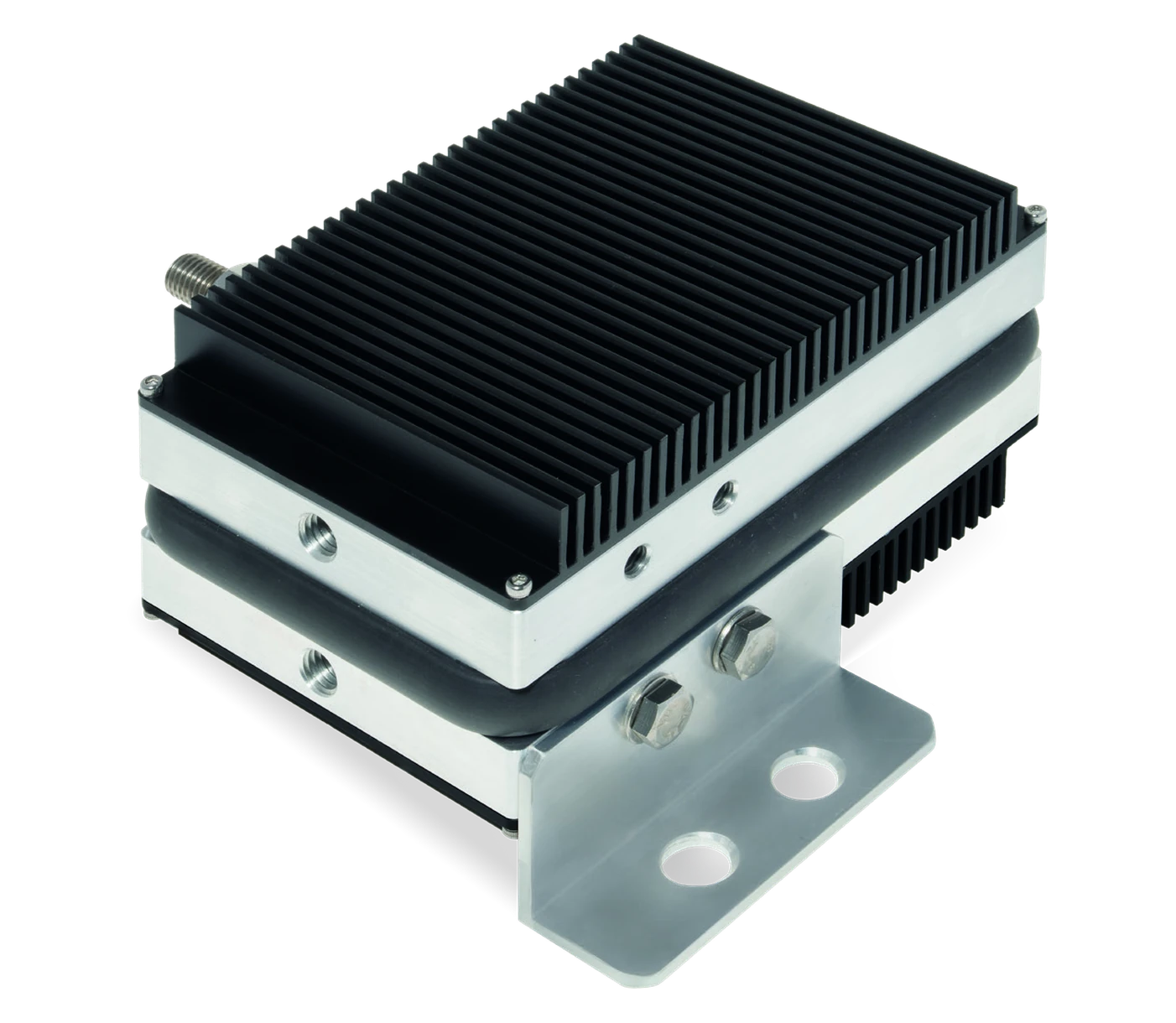
RWVL2.1HP
Recoverable short‑time current
The world's highest published recoverable short‑time current identified in VLD class 2.1: 34 kA at 50 ms.
- 24 kA recoverable at 100 ms
- More than 3 kA recoverable for 30 seconds
- 60 V, 120 V and 350 V triggering variants
- Body and HS versions with heatsinks
Building on a world‑leading 25 kA platform. RWVL2.1 already held the market‑leading position at 25 kA at 50 ms. The new RWVL2.1HP raises this recoverable rating to 34 kA, an increase of 36%.
The comparison concerns published recoverable short‑time current ratings in VLD class 2.1, not non‑recoverable fault or impulse ratings.
Model comparison
Technical data
Values below apply to the 120 V versions. HS denotes the version with heatsinks.
Scroll horizontally to compare both models →
| Parameter | RWVL2.1 | RWVL2.1HP · NEW |
|---|---|---|
| VLD type / class | VLD‑O+F / class 2.1 | VLD‑O+F / class 2.1 |
| Traction system / switching polarity | DC / one primary switching polarity | DC / one primary switching polarity |
| Recoverable short‑time current at 50 ms | 25 kA | 34 kA |
| Recoverable short‑time current at 100 ms | 18 kA | 24 kA |
| Recoverable long‑time current at 30 s | >3 kA | >3 kA |
| Non‑recoverable short‑time current at 100 ms | >40 kA | >40 kA |
| Rated current, 60 min (body / HS) | 130 A / 170 A | 130 A / 170 A |
| Nominal triggering voltage UTn | 120 V | 120 V |
| Instantaneous triggering voltage UTi | 200 V | 200 V |
| Non‑triggering voltage Uw | 110 V | 110 V |
| Reverse voltage Urev | 350 V | 350 V |
| Residual voltage at Ir / Iw / Iimp‑n | 0.9 V / 15 V / 900 V | 0.9 V / 15 V / 900 V |
| Leakage current at Uw | <2 mA | <2 mA |
| Lightning impulse current, 8/20 µs | 40 kA | 40 kA |
| High‑current impulse, 8/20 µs | 70 kA | 70 kA |
| High‑charge impulse, 10/350 µs | 25 kA | 25 kA |
| Response time: surge / thyristor UTi / UTn | 25 ns / 1 ms / 10 ms | 25 ns / 1 ms / 10 ms |
| Operating temperature | −40 to +70 °C | −40 to +70 °C |
| Protection / environment | IP66; indoor/outdoor; UV and salt‑spray resistant | IP66; indoor/outdoor; UV and salt‑spray resistant |
| VLD power supply | No external power supply required | No external power supply required |
| Monitoring option | Wireless (IoT) voltage and current monitor; LTE‑M (NB‑IoT) | Wireless (IoT) voltage and current monitor; LTE‑M (NB‑IoT) |
| Weight (body / HS) | 3 kg / 4.2 kg | 3 kg / 4.2 kg |
| Product standard | EN 50526‑2 | EN 50526‑2 |
| Ordering number, 120 V (body / HS) | VL21120 / VL21120HS | VL21HP120 / VL21HP120HS |
| Customs tariff | 85301000 | 85301000 |
Rated current: 60 minutes at 25 °C ambient with a 75 K temperature rise. Thyristor triggering delays are factory adjustable. Recoverable current ratings and non‑recoverable fault withstand are different parameters; impulse ratings refer to the stated µs waveforms.
Trigger‑voltage variants
| Variant | UTn / UTi / Uw | Ordering numbers: RWVL2.1 / RWVL2.1HP |
|---|---|---|
| 60 V | 60 V / 120 V / 50 V | VL2160 / VL21HP60 |
| 120 V | 120 V / 200 V / 110 V | VL21120 / VL21HP120 |
| 350 V | 350 V / 350 V / 310 V | VL21350 / VL21HP350 |
| Project‑specific | UTn and UTi: 20–350 V; Uw: 15–310 V, on request | VL21xxx / VL21HPxxx |
Add HS to the ordering number for the version with heatsinks. Select triggering voltages for the installation and applicable national requirements.
Selecting class 2.1 for the application
DC traction and one primary polarity
Class 2.1 uses a power thyristor for its primary switching polarity. The integrated varistors provide surge protection. The VLD requires no external supply for its protective function.
Application review must cover polarity, return‑circuit conditions, regenerative operation and the expected fault current and duration. Longer reverse‑polarity loads can overload the varistors; a higher forward‑current rating does not make class 2.1 bipolar.
For repeatable operation in both voltage polarities, consider RW class 2.2 devices. Compare operating principles in the VLD comparison tables.
Online measurement and monitoring
Optional RWVLM monitoring measures rail‑to‑earth voltage and VLD current and communicates via LTE‑M (NB‑IoT). Fault notifications support targeted inspection and replacement of the affected device.
Prompt identification and replacement of a failed, continuously conducting VLD can shorten the period of stray‑current flow and help reduce the associated corrosion risk. The monitoring unit requires its own power supply.
Read more about railway VLD technology →
Discuss your DC traction application
Send us the traction‑system details, required triggering voltage, expected fault‑current profile and monitoring requirements. We will help select the model and configuration.
Contact technical sales